)
)
)
)
)
)
)
)
| NEW |
| Original Wiring | Diagrams | Cruise Control | Painless Re-Wire 2017 |
LED Headlights |
)
)
)
)
)
)
)
)
)
)
These are shots of the wiring before and during the editing process. It looks worse than the job really is. I started by stripping all the tape off and laying out the harness in the general area where I wanted to route it. I've moved the fuel relay into the upper pedal area and pulled all the computer harness through the large 3" grommet to inside the footbox. The front system is laid out along the inner frame rail, but is going to the outside (wheel side) on the final run. I did this to get an idea of what was needed. I'm using the fog lamp wire to power the running light in the headlamps. All exterior lights are working and ready to plug in when needed. The low oil level wire is being used for my oil temperature gauge. The computer and rear harness is routed through the access hole at the top of the footbox near the tunnel. My master cutoff switch is located behind the drivers seat along with the proportioning valve for the brakes. These can be accessed by the right hand by just reaching around the seat. The last picture is the leftover wire, belt and switches I won't be using.
)
)
)
)
)
)
)
)
These are shots of the heater and wiring for the O2 sensors. I routed the O2 harness down the back of the engine and then underneath the car at the bell housing. This makes for a clean install and the wiring is protected and out of site. The next pictures are of the heater installation. The dash has it's initial gauges installed and the toggle switches, heater, headlamp and ignition switch will be connected when the dash is installed. They are attached to the chassis at this time. The other is the back of the dash.
)
)
)
)
The shots above show the routing of the O2 sensor harness and how it's tied to the lower two bell housing bolts with straps. This keeps the harness out of the engine compartment and out of the way of heat and road damage. The connectors have plastic retainers (you can get replacements from Ford or a good parts store) and they are held to the frame below the motor mount by drilling a hole to press the retainers in.
Electrical Diagrams
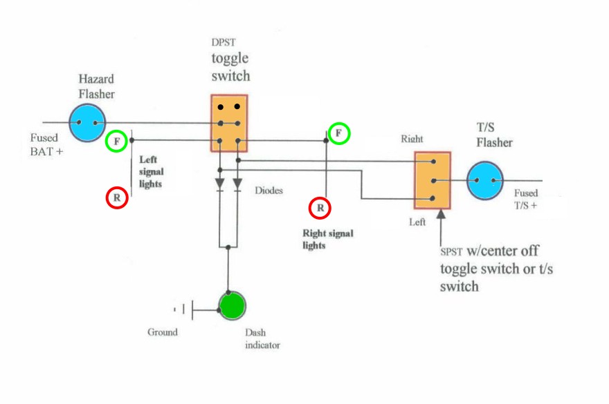
The turn signal diagram can be utilized using either the shown toggle switch display, or, by adding the column mounted switch. The wiring will not change. This is setup for one indicator lamp. If you decide to use two indicator lamps, you will not need to use any diodes.
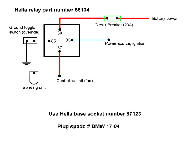
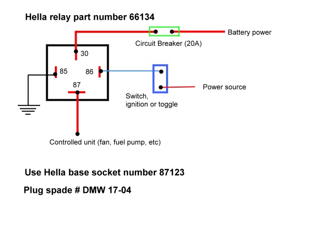
The following relay setup can be used to operate automatically, and/or, with a manual toggle to override the feature. I use this with my cooling fan system.
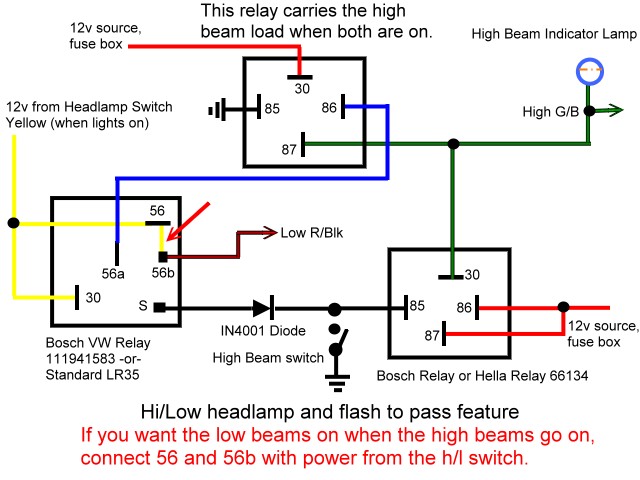
This is a modified version of the "low/high" headlamp system. If you wire it as I have shown, both low and high beams will work at the same time when you use your high beam lights. If you wire as shown on other sites, you will not have all four lights burning at the same time, thus cutting down your night vision area.
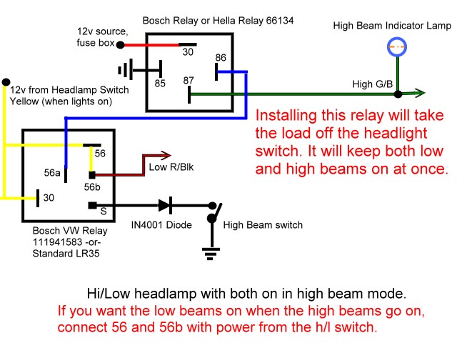
The following diagram is for "low/high" without the "flash-to-pass" feature. Both systems use a jumper wire to allow the low beam lights to stay on while having the high beam on. Using the extra relay will put the load separate from the dimmer switch relay and not overheat your relay or headlight switch.
This is a stand alone automatic relay function.
This is the wiring schematic for the Honda S2000 start button that some are using.
Cruise Control Unit
March 2009
One of the best "mods" I've done to the car since the build!
I took time and researched the use of a cruise control unit for the car. I thought it would be very helpful on the long trips we take. A few others have used the Audiovox CSS-100 so I bought one and installed it beofre our long trip accross country in 2009.
I was using the Mass-Flo setup at the time of installation so I needed to make a simple extension to the throttle bracket to secure the cable. Routing the cable is just figuring out where to put the servo and have the cable come out where you need it. I found putting it on the right side w/s post bracket worked out just fine.
Since the writing and cross country trip, the picture is on a Holley Terminator EFI setup, but is similar to a carburator linkage.
Wiring was pretty straight forward. Connect to coil, VSS sensor, ignition, brake switch and control switch (provided with kit). I ran the wires through the small panel near the passenger w/s bracket. A small 3/4" hole for a grommet worked fine. I then ran the wires accross the top of the 2 x 3 inch tube to the fuse panel area for the connections. Tapping in the circuits at the computer mounted on the right side of the car made the tach and VSS connection easy.
The dip switch settings were as follows: 1-on, 2-on (controls VSS counts); 3-off (Tach); 4-off, 5-off (control sensitivity) 6-off, 7-on (coil). The Ford VSS has a 8,000 ppm (pulse per mile).
Going for a test drive everything worked fine. Be sure to get at least 35mph before setting the speed. Accelerating with the control unit is just a simple touch of the rocker switch and/or hold it down to get more speed faster. The resume featured just as good being able to accelerate and then resume to your originally set speed.
NOTE: If you're not using a MSD or other ignition box, you can leave dip switch 3 to off and not use the VSS signal. The unit will work just fine.
)
)
March 2010
I recently re-did my engine due to a bad build from GMP in Santa Cruz. You can read about that here: Engine. This prompted another change on the cruise control becasue I switched to the Powerjection III unit, which required another change on the servo/cable assembly routing and I also installed a MSD 6AL-2 ignition box (more on that).
I had to re-route the servo so the cable would go along the firewall and then connect to the throttle linkage just below the throttle cable position.I removed it from my w/s post area and moved it to just forward of the passenger footbox on the 3/4" tubing. This will keep the cable pull for the cruise at a non-binding angle when working. Also, remember to keep some slack in the cable when at idle position so the cruise control unit doesn't effect the throttle stop or idle positioning.
I mounted the MSD ignition box to the right side of my heater on the firewall. This will keep it out of the way of anything and let air still circulate around it. I made the adjusting plugs accessible to change the RPM setting if necessary.
All the wires were then sent through the same grommet as before and into the cockpit of the car. I connected the tach wire to the gray MSD wire (DO NOT connect anything to the - coil with a MSD box installed) and routed the VSS wire to the transmission VSS sensor on my speedometer cable. The other side of the VSS sensor should be grounded to the frame nearby. Be sure to have dip switch 3 set to the ON position, if you have it set to tach only (which will work), the cruise control unit won't work with the MSD tach output, the frequency is different. When I had it previously installed I didn't realize I was only getting the tach signal and not the VSS in conjuntion. While trying to get the system to work as before, I found I had to have the dip switch set to ON for 3. Now, the switches are set as follows: 1-on, 2-on (controls VSS counts); 3-on (Tach & VSS); 4-on, 5-on (control sensitivity); 6-off, 7-on (coil-although it really doesn't matter with the MSD box.)
If you need to make adjustments to the activation part of the cruise, you can experiment with dip switches 4 & 5. These control how sensitive you want the unit to react. I find the medium works fine with a high horsepower car, which would be OFF/OFF respectively on each one. Although mines set for ON/ON, either one works fine.
The system is working fine again. I gave it another good test and only really use it on long open stretches of highway. It's nice to give your leg a little rest now and then and makes the trip that much more relaxing.
As of this writing, the Audiovox CSS-100 is no longer being made and is acutally made by Rostra. If you can find one, they're priced about $250.00. I only paid $89.00 when I bought mine! Dakota Digital ($250.00) PN:CRS-3000-2 is available from Summit Racing and will work as well. The bonus with this one is it's ALL electric (no vacuum), works with MSD for tach and goes to 36,000 ppm's. This will help with the Tremec speedometer pulse adapter which I believe is set to 12,000 ppm's. If you still use a cable driven speedometer, and use a Tremec, you can still purchase a VSS sensor and set the unit to 8,000 ppm's. The Dakota Digital unit comes complete with everything you need. If you buy the Rostra compatible unit, you have to buy the control switch extra, but they both are about the same price as the Dakota Digital unit. Oh, the Dakota Digital unit is also made by Rostra. Go figure.
March/April 2017
Entire Re-Wire
The start of the entire re-wire of the car has begun. In conjunction with doing the "backbone" and passenger footbox re-size, I pulled all the old wiring harness (my Ford dieted one, which is going in another car) and started installation of the new Painless Performance wiring harness. I'm using their 10101 kit for the job. Not much has happened because of multiple projects, but the harness is getting positioned so I can start some work. I have my car "hot wired" right now so I can move it. Just using a ignition switch to fuel and spark. Really all that's needed to move it around. I can continue with the new wiring without connecting to the battery...YET.
Started getting serious now that the TKO500 is finally installed. Had most of the harness layed out for routing but had to wait until the transmission was in before finalizing wiring to the rear. First thing I did was make a small plate to cover the hole that was originally in for the Ford harness. I had it weather tight, but this time I wanted a grommet. After that it was routing down the tunnel to the rear. I followed my old route about the same but now that the backbone is in, I was able to run it closer to the top and secure it and the Holley Termiantor harness much neater. I also will be using the Holley system to run the fuel pump so I ran it's wiring into my Painless harness from below the trunk area where I have the Holley computer mounted.
I made a new "removeable" mount for my Cruise Control module because it was just VHB taped to the frame and I wanted to be able to remove and repair/replace if needed. I also used Metri Pack plugs to route all my wiring under the dash. It will be removeable so I had to plan carefully so I didn't overlook anything. I have a couple of "special" plugs I'll be using occasionally so those are getting wired in as well. I'll have a total of three plugs to control gauges, toggle switches and dash lighting (indicators too). By doing this, I'll just unplug the three connectors, remove the ignition and headlight switch and drop the dash.
I did another mid-redo of my fuse panel bracket. I have another plan coming up that required me to make a new one. I'll be doing that before the project end so stay tuned.
Marked out my new blank dash for gauges and switches. The layout was going to be the same but I still had to place them correctly. A lot of measure twice, think three times, measure again before finally "going for it". Happy it turned out in my favor. I'd hate to mount the dash again from scratch. I'm using Autometer Sport Comp II gauges with LED lighitng this time. The speedometer will be electric as well.
Wiring about 99% completed (mid April) and just have to finish light plug ends at corners. A lot has been done in the last week and I can see the "light" so to speak. Finalized all the dash connections, heater, seat heaters, cruise control, courtesy lights and power plugs. I put a lot of thought into doing it ALL so I don't have to add something else, but do have options for future circuits if needed.
Behind the dash will get tiddy after removal, but I can remove it and still run the car (sans gauges) which was a main objective. All the plugs are Metri Pack and color coded. The four plugs, light switch plug and ignition switch are the only things that need to be removed or unplugged to remove the dash. This took the most time to figure it all out.
) |
) |
) |
) |
) |
) |
) |
) |
) |
) |
) |
) |
) |
) |
Finishing up final wiring. I put two power plugs in the under dash supports and they're running off the ACC side of the ignition switch through a 30A circuit breaker. This is all that's connected to the breaker at this time. I also had to change the T/S plug, adding the two "ground" wires that run the high beam circuit. I also cleaned up the harness and secured the extra circuits from the fuse panel. The door jamb switches will be added after I put the body back on and get the doors adjusted. I'll need to add a "tab" to the hinge to activate the switch and I've put the wire in the 2" down tube and will fish it out through the switch hole later.
The dash is being covered now and I'll be installing all the gauges and switches when I get it back. It only took about 10min to get out. Much nicer with the "plug-n-play" system.
LED Headlights
I'm using Kensun LED headlights on the car at this time (Jun 2016). I've tried several brands and the first from Kensun weren't that good so they kindly upgraded my lights to these. The ballast is much smaller and can fit behind the lens in the "bucket" without the need to have wiring outside the enclosure. I can also run low and high beam at the same time by using the Low/High wiring diagram shown above, without the "flash-to-pass" feature. I don't feel the need for that so I choose not to. However, I do show how to wire that in as well if you prefer to have both options.
) |
) |
) |