
| Project Start | Coyote Engine Installation | Wiring Layout | Fuel Line Fabrication | Cooling System |
| Power Steering | Air/MAF Intake | Exhaust Changes | Thoughts and Analysis | Fuel Tank/Modification |
| Holley Coyote Oil Pan | Holley Coyote Oil Pan...LEAK |
April 2022
Finally beginning the Coyote swap into my SN95 GT. Plan is to use the Gen I 2013 donor stock PCM, engine w/stock tune. I will run a return-style fuel system with new pump and regulator. I'm using a Power by The Hour front drive setup to make things a bit easier, along with a Power by The Hour body harness. Doing this will speed up my timeline and save countless hours of going through the donor just to have a returnless system.
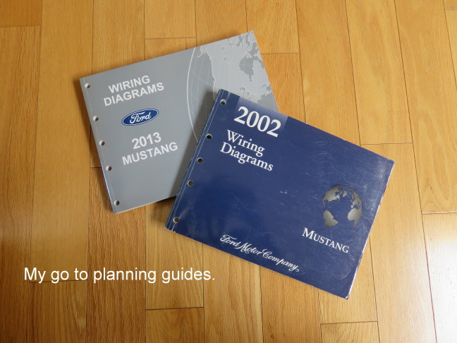
I spent hours going over other builds/swaps on internet forums as well as YouTube videos and many have a lot of good information and help. The only thing I wish they'd do is finish explaining what they did. Many of them say "you just have to do this and that" but never say what they actually did. I find that amusing like it's some kind of secret. My build isn't going to be like that. I intend on doing a good job of documenting/photo/video the work I do. I have nothing to hide. The biggest hurdle is the wiring and mating the donor with my stock GT. One thing is a must if you choose this route and that's a good wiring diagram of your vehicle and if you can, the donor if you use one.
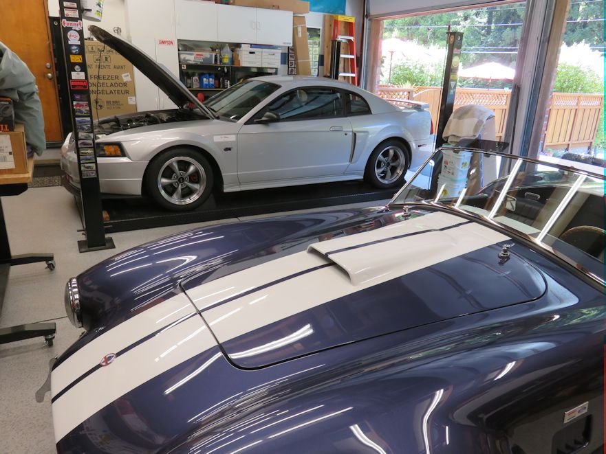
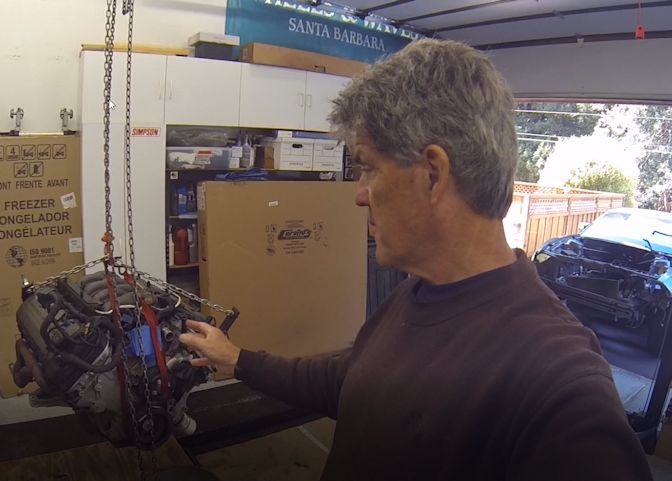
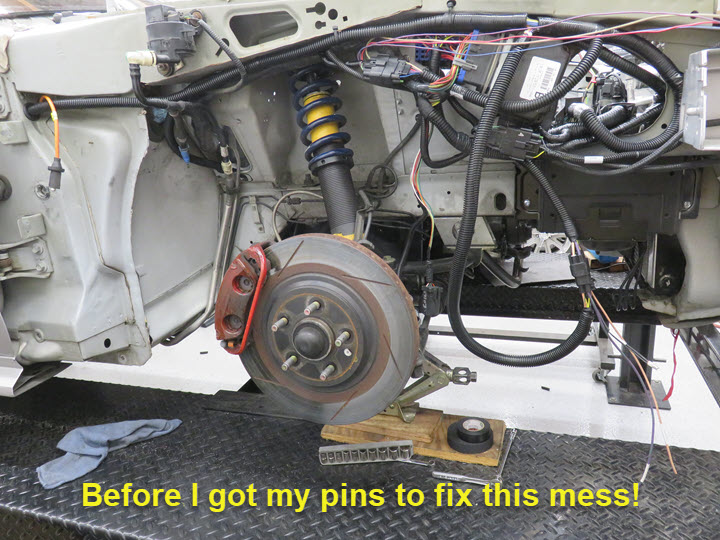
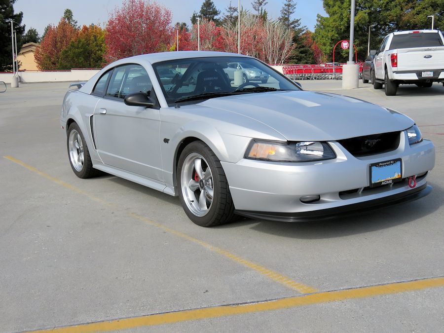
For starters, this is the current 2002 Mustang on my rack. It's still in operation and will not be disturbed until I'm fully ready to do the transfer. I have some minor engine work to do on the 2013 (oil pump gears/sprocket) once the engine comes out. Using the Power by The Hour Speed Drive allows me to retain my stock power steering, air conditioning and moves the alternator to the right side. I'll have to wait to see which de-gas tank I use and my goal is also to keep the battery in the engine compartment.
There's a few things needed to tie into the existing 2002 chassis to make things work. I want to keep my stock SN95 dash and gauges so that's where I'm starting with wiring. Just figured out (on paper) the flow of oil, voltage, water temperature, tachometer and fuel. The speedometer will be using the stock T3650 transmission OSS and that signal goes through the stock PCM. Tachometer will flow though the stock PCM as well but will be "tapped into" the Coyote so it'll work. I won't be sure of anything until I turn the key to fire it up and that's a few months away.
Doing this project is not for the weak of heart or pocketbook by any means. I'm not sure why/what prompted me to do this other than being tired of getting passed on track by cars that can't catch me when I'm in the Cobra. So I guess it's just a little of both greed and pleasure. Not a bad combination. Also doing this project mainly by myself (unless I persuade a few friends now and then) will give me a sense of satisfaction.
Project Start
Work started on the removal and teardown of the Gen 1 Coyote engine swap. I pulled the transmission (not being used) and finally the engine and started with upgrading the oil pump gears, crank sprocket and timing chains. I'm documenting this project on My YouTube Channel to share as well as putting as much information here as I can.
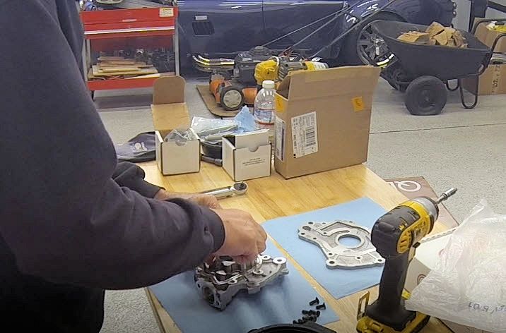
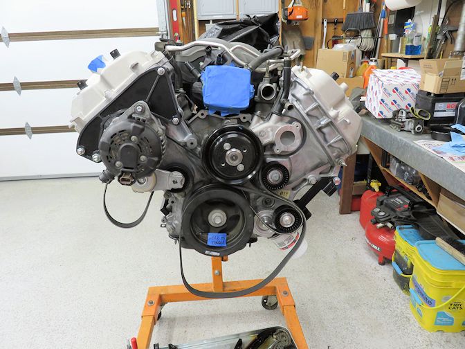
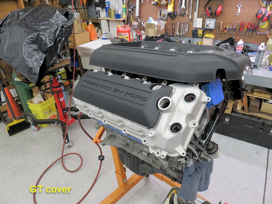
Basic start was to get the harness and covers off the engine while I upgrade the parts and do a fitment check on the Power by The Hour Speed Drive assembly I'll be using. I'm taking my time as I go but the goal is to have it ready for the track in early August this year. Most of the tedious stuff will be once it gets installed in my '02 GT, but I have no doubt it'll turn out just fine.
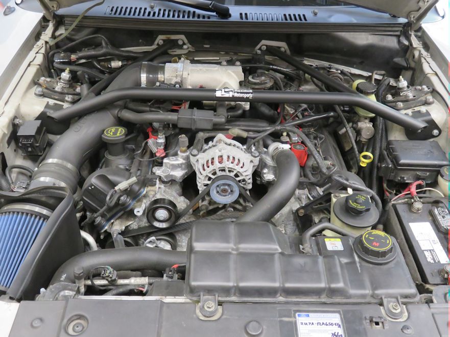
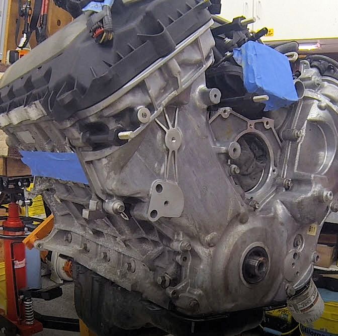
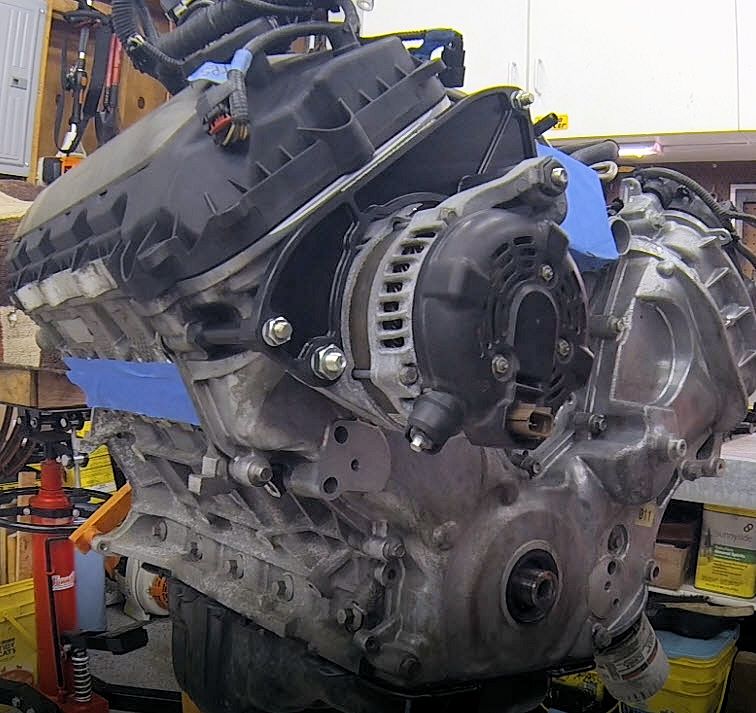
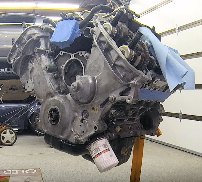
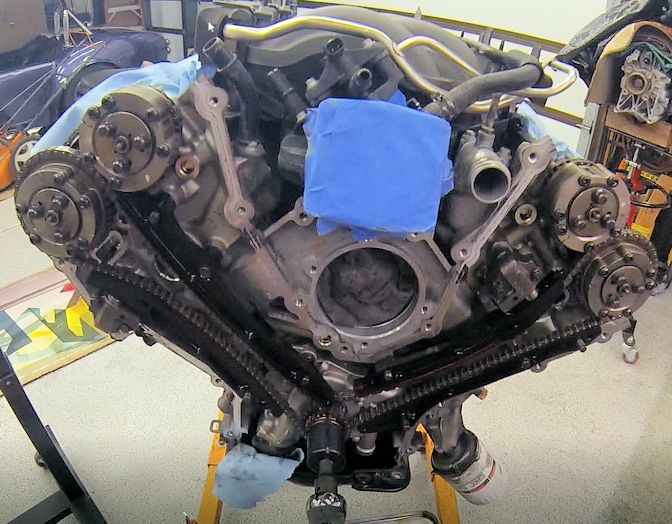
A few pictures of the engine out of the donor and the fitment of the alternator relocater brackets from Power by The Hour and the timing cover and chains. My goal is to put new chains and tensioners on, even though the engine only had 85k miles, along with the updated oil pump/crank boundary gears.
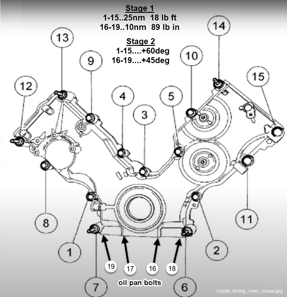
Without going into a lot of detail, teardown/installation process isn't that hard. There's so much right/wrong information out there, that a manual is your best friend. My goal is to NOT give the wrong information when doing things and I prepared a document (straight from the Ford manual) that covers each step on a Gen 1 Coyote for the process.
As I write this the cam sprockets are on national backorder and if I can't get them prior to me buttoning up the engine, I'll do that in the car later. Yes, I know the whole front will need to come off again, but all I have is time. As it turns out, that's exactly what I'm going to do. If/when parts are available (thanks Ford), I'll tear it apart in the car. I need to get moving on this project.
After striking out on getting a complete timing chain/gear set, I spoke with Power by The Hour and they said they I shouldn't't have any problems and they do it all the time. Plus, the engine only has 85k miles and it sounded good prior to the teardown. So, I'm putting the stock stuff back on and if it's an issue later, I'll tear it apart in the car. Nobody seems to think Ford is going to make this stuff for the Gen 1's so I'm not sure what I'll do later.
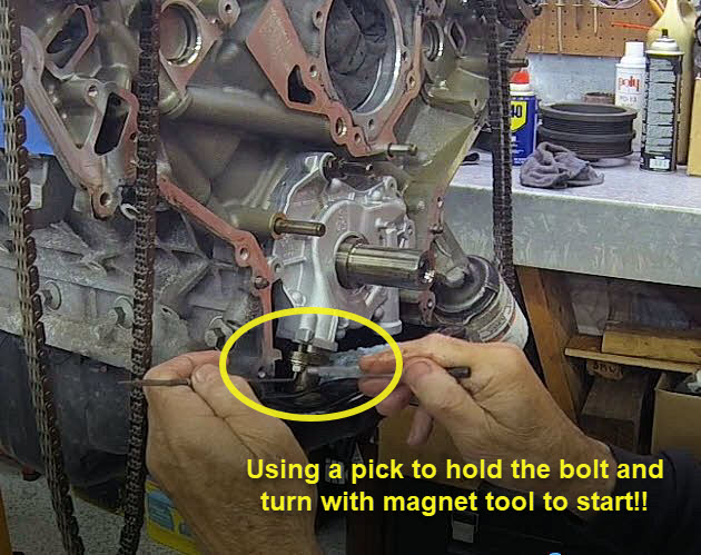
Removing and installing the oil pump pickup tube bolts is a little nerve racking, but all good. I did something similar on an LS3 in a Camaro while it was in the car. What a job! That's where I figured out how to ge the bolts in/out. Yeah, I had more room but just take your time and it'll be fine. I put a shop towel to catch the bolt if anything went wrong, but it didn't. Putting it in is just as easy. Start one pump bolt to just stabilize the pump and then put the tube in (with the "O-ring" on the tube) and use the magnet to locate and then the pick (or something similar) on the head of the bolt and start it with the pencil magnet. Piece of cake!!

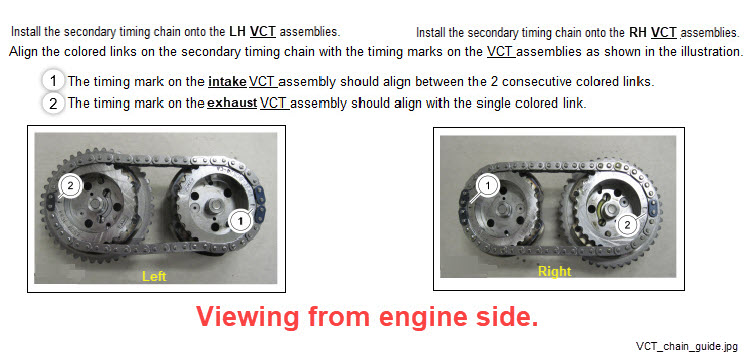
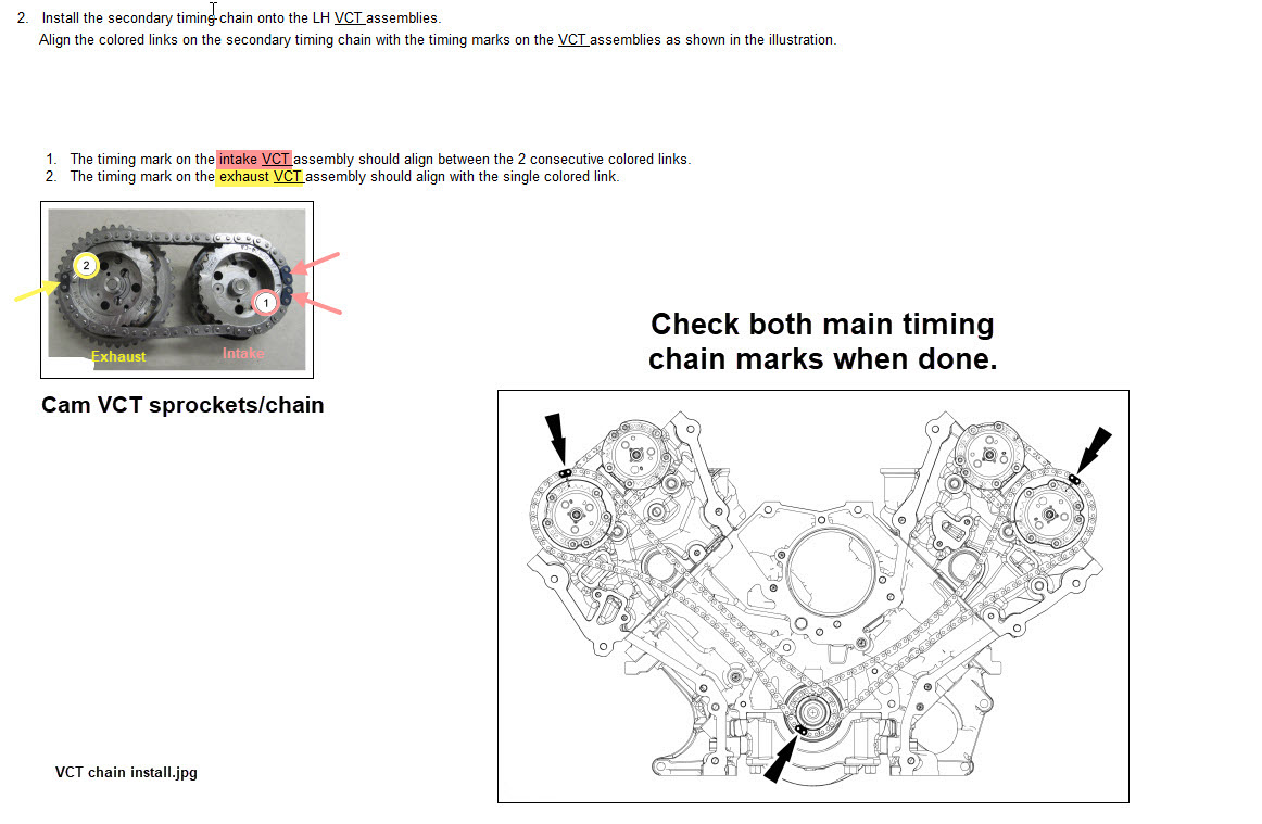
Assembling the chains isn't that difficult, just nerve wracking. If you've never done one, it is intimidating, but there's some good information out there, you just have to find it. Or, you can purchase a quality engine manual to guide you along the way. Better yet, I have it all right here!
The key is to be patient and be thorough, then double check your work. The following pictures have enough information for you to do it right.
Engine Installation
Next order of business was getting the engine in the chassis. I know the "easy way" is from the bottom, but that's if you have everything installed and you know it fits. In my case, I wasn't sure but did know I could install it from the top (without the headers), so that's how my plan of attack was going to happen. I left the alternator off and installed the engine without any big hurdles, although it was/is a tight fit. Main things to watch out for is the brake master cylinder level plug and the A/C lines. The rest is just taking time to get it in place. I use a chain hoist setup and I was able to put it in by myself.
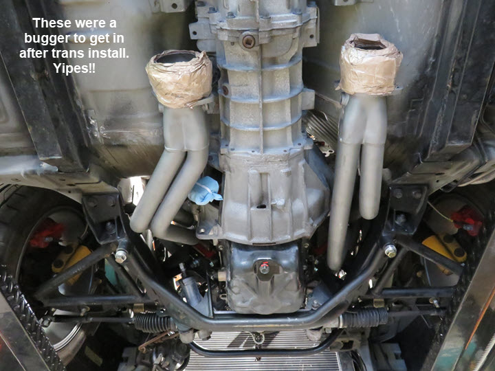
Once the engine was in I needed to see how the headers fit. There is room, but boy is it tight. I've seen people put the engines in from the top with the headers on too. I spent about four hours installing the headers due to clearance issues getting a few of the bolts. Also, you need to have the transmission/clutch assembly installed prior the headers because there is NO room to fit it after the headers are installed. In my case the transmission had to be installed because I'm using my TK3650 which is the same as putting an automatic in. Then you can install the headers and maneuver around the transmission at the same time. Lot's of fun. Be sure to remove the steering shaft. Now for the important part...
I needed to raise the transmission/engine assembly at least an inch to get the headers and bolts in. Also, the right side motor mount was removed for better access to bolts. If you left the studs in the heads, you're going to regret it because you can't get the headers on from underneath with them installed. So, take all of them out and use bolts to secure the headers, even if you install the package from below. Also, put the starter on while you have the engine raised or you'll be raising it again to get the starter past the "K" member and exhaust. Once it clears, not an issue and you can move it around, it's just getting inside the headers. In my case, I did mine after and just had to raise the engine about 1" to allow the starter to slip by the "K" member. I did the right side first which is the harder side to do. The driver side is much easier and you have more clearance. Once they're in, put the steering shaft back in.
Wiring Layout
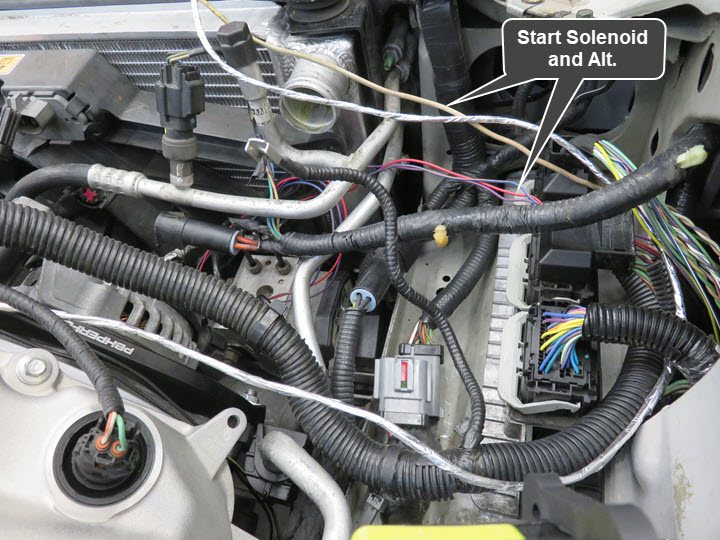
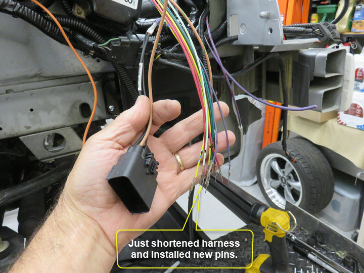
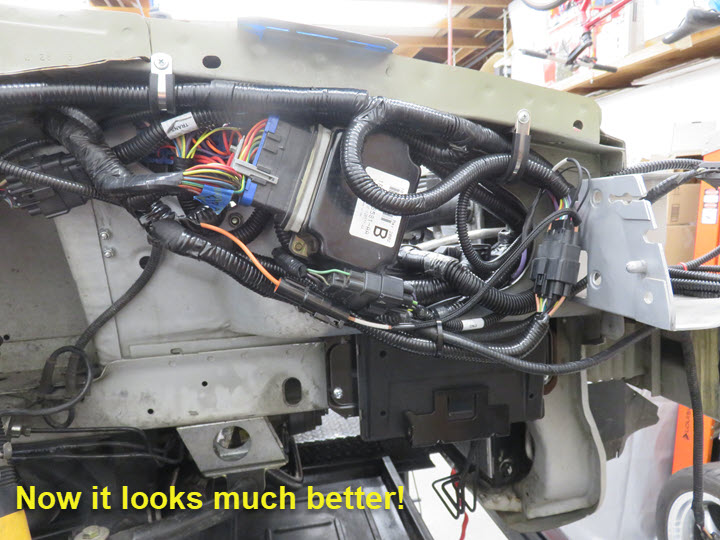
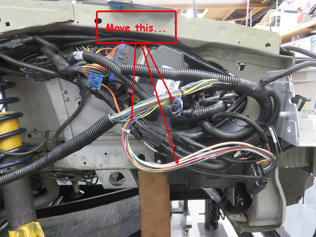
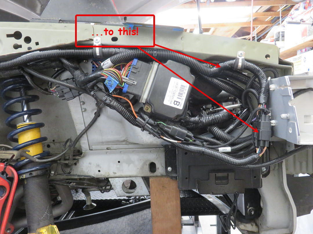
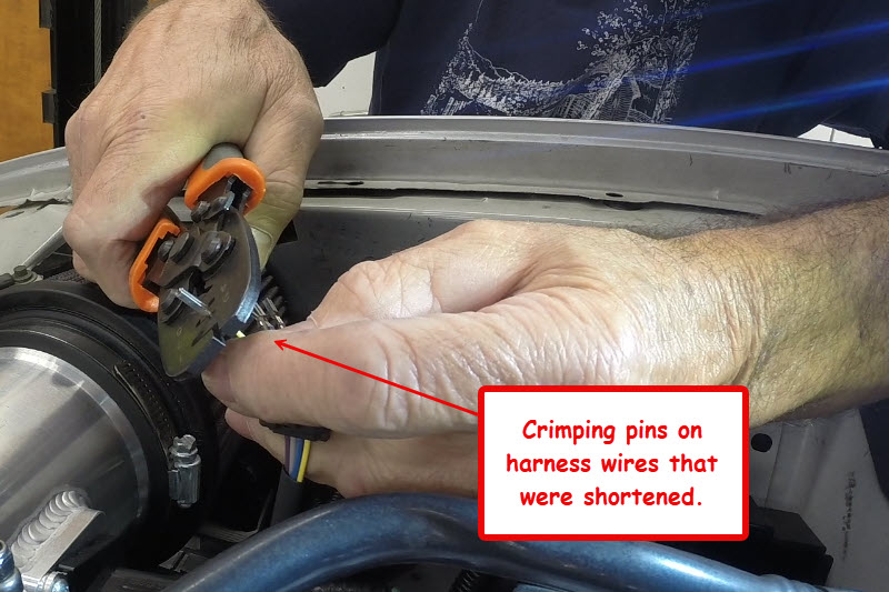
Next in line was laying out the harness and figuring a good way to route both the Coyote and chassis harness's without having issues. As I mentioned earlier, get both wiring diagrams/manuals for the project. You'll thank yourself later. Or, find a good person to help you that knows how to do it. Once you have a plan, you may change it a few times, I know I did. I also did a lot of shortening and re-routing of both the Coyote and chassis to allow me to obtain and nice clean look. I really hate seeing looms looped up and then zip tied to take up the slack. I either shorten the runs by splicing/solder/heatshrink, or better yet, getting the correct pins and de-pinning the terminals and shortening right at the plug!
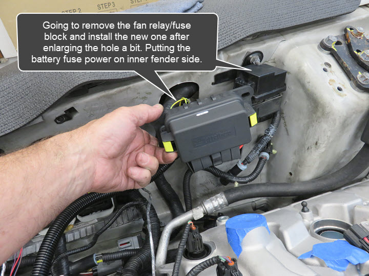
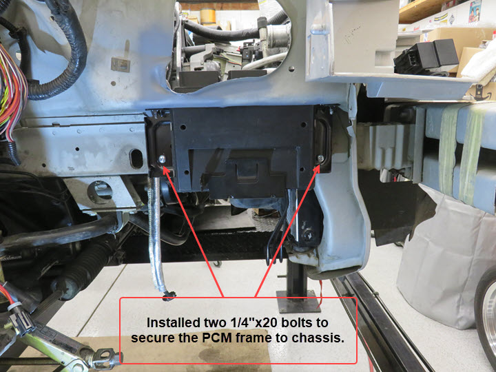
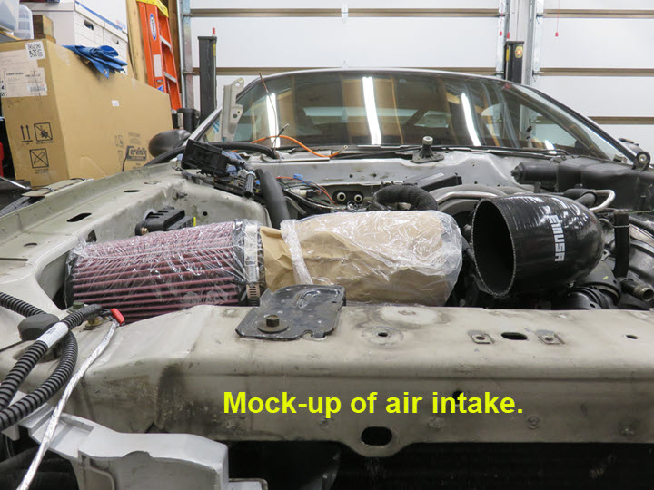
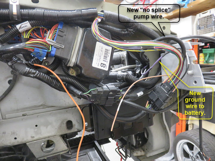
I decided to put ALL of the fuse block and Mega-Fuse inside the engine compartment. This will make any servicing a whole lot easier than having it stuck under the wheel well behind the splash shield. Not a real good area to get to when/if you have a problem. The other part was figuring out where to put the PCM. I wanted to have my original look under the hood with the battery on the driver side so planning was top notch. I figured I could mount it below the frame in the area where the air intake was on the stock 4.6 and then cut out the needed area to fit the PCM. I used my donor PCM bracket to help secure the PCM to the chassis. This allows me to remove the PCM from the top (under hood) for any repairs if needed. Just another way to make things accessible. I also tested placement of the Mass Air Flow sensor and intake tube. It'll fit very nicely to the right side just as the "stock one" did, which allows me to keep the battery on the left front side!
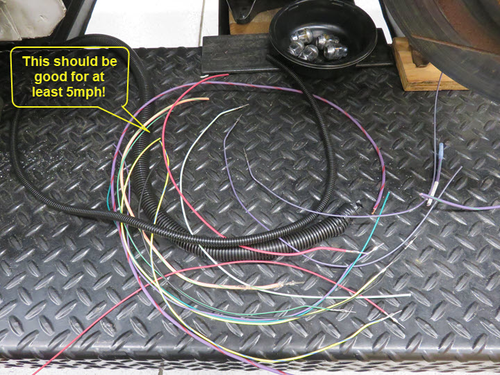
After a lot of figuring out how I was going to run the harness(s) I finally came up with a satisfactory routing and then just needed to shorten them. The harness has WAY TOO MUCH wire and I'm not a fan of wrapping and zip tying them like so many others do. I also wanted the system to be fully manageable and easy to work on if needed. I sourced connectors and pins from either Mouser Electronics or EFI Connection. Both of these sites have done well for all my needs. The biggest hurdle is knowing what connector you have or want to install. Once I knew that, the rest is easy.
I will tell you the 16pin connector in the harness (the one with 4 large wires at the corners) is a Molex 150 Hybrid. Hybrid meaning it can take different size pins. It can take three different pins. In this case, it takes a standard 1.5mm pin (12) and (4) 2.8mm pins. Now you know.
M=male F=female
1.5mm
M: 33000-0002 Molex
F: 33012-2001 Molex
2.8mm
M: 1326031-5 TE Connectivity
F: 1-1326032-1 TE Connectivity
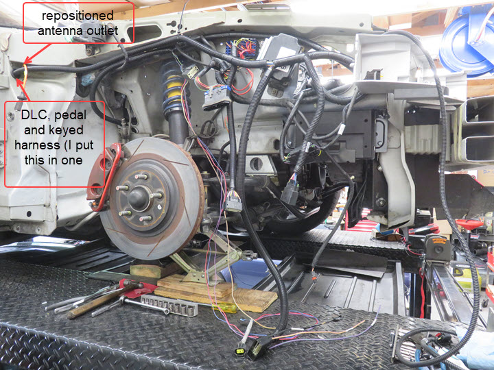
After routing the harness to the interior to control start, ignition, DLC, throttle and transmission features, I ended up shortening at least four feet off the DLC, throttle and power leads. This made it a much cleaner install but still allowed for any repair work if needed, which I hope never happens. I didn't have to route wires for the speedometer, fuel, oil, water etc. because all that was being done through the stock ECU and I'm using stock gauges. Much of this work is video documented on my YouTube Site.
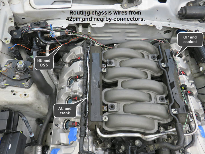
One issue I ran into while wiring and "trying" to start the engine for the first time was the tach signal not working and the engine just able to crank only. I had oil pressure, voltage etc. but no ignition! After scratching my head a bit and double checking my wiring, I temporarily disconnected the 42pin connector I dieted, which had the crank, oil pressure, AC and water temperature running through it. The engine fired right up!! I knew I had oil pressure and voltage so it had to be the crank signal. Once I disconnected that circuit, the engine fired up, but still no tachometer.
Doing more research I found that on a Gen 1 engine (at least) you don't connect the negative crank signal wire to the Coyote harness. You leave the positive (+) wire connected only and the shielded wire is definitely NOT connected but left in the harness. The negaitve (-) signal wire is just left terminated and NOT connected to the Coyote harness. This is due to me running the stock '02 Mustang dash assembly. Basically, the positive (+) crank signal wire from the stock Mustang GT PCM is connected to the positive (+) crank wire on the Coyote PCM harness. After doing that, the engine ran fine and the tachometer worked. All good in the neighborhood!
Running Fuel Lines
I'm really trying hard to get this completed before my big track event in August. It's our club's biggest event and although I know at some point this will be ready, I'm semi confident I'll make it with the car. If not, I have my Cobra to fall back on, which isn't a bad option to have.
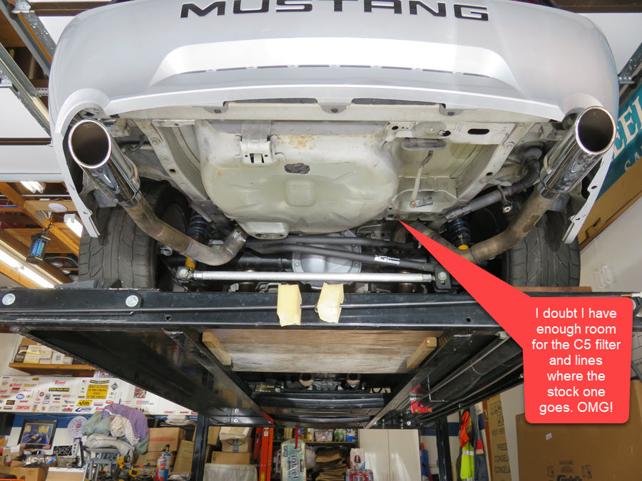
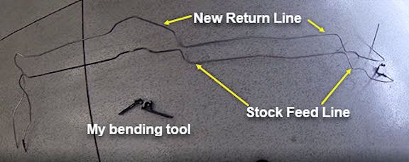
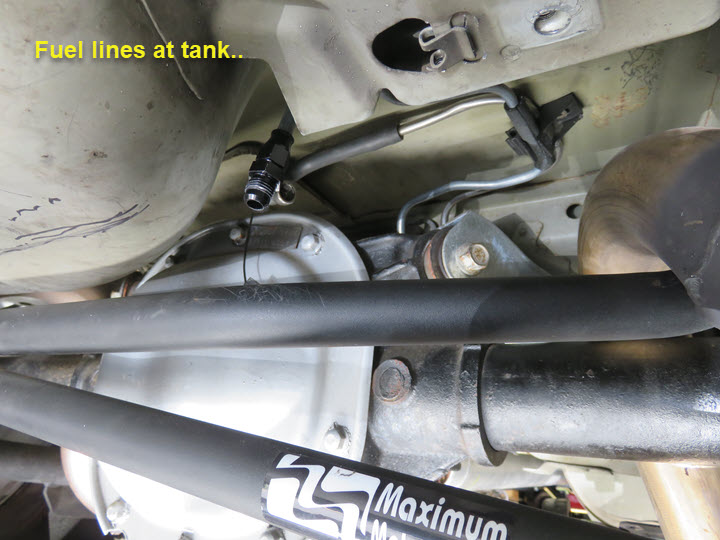
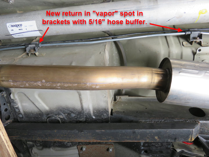
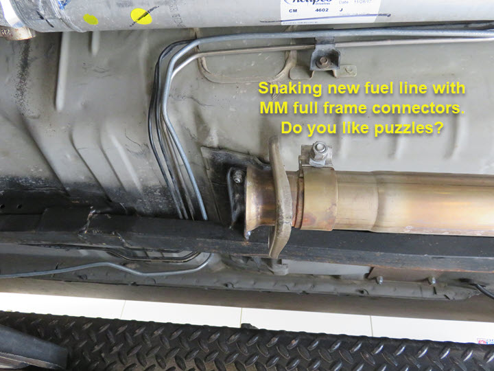
I'm pressing forward with the fuel line setup. I originally planned to use the Corvette fuel filter with built in regulator, but with very limited tight space in the rear with my Panhard Bar setup,that was going nowhere fast. So, next option is to run a new return line to the front of the car. I know running SS braided line is easy, but that's not my style. I opted for a new hand built steel line to run under the car. Doing this is not easy and having full frame welded in Maximum Motorsports connectors doesn't allow you to "simply" remove solid lines. So, I snaked them in and out from under the car without bending a single one. I took both the vapor return line (not needed) as well as the stock feed line (using as my template) out and using the stock feed line, copied a steel line to use for my return from 5/16" tubing.
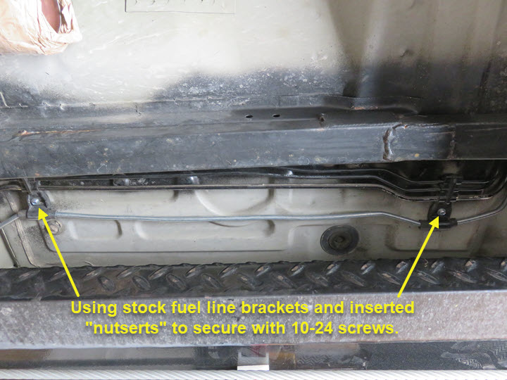
This took me about 4 hours to bend and needed the entire side of my garage so the line could "whip" back and forth as I made my bends. I was very pleased how it turned out and then proceeded to install the line for fitment. It fit good and although my ends needed trimming, I was pleased. The rest was just securing to the existing brackets and using some 10-24 nutserts to secure them back to the chassis after drilling out the rivets. This way, I can easily service all the lines running in them. The rest was just getting the right length at each end and using 5/16" compression AN6 fittings at each end to secure my fuel braided lines I need to make.
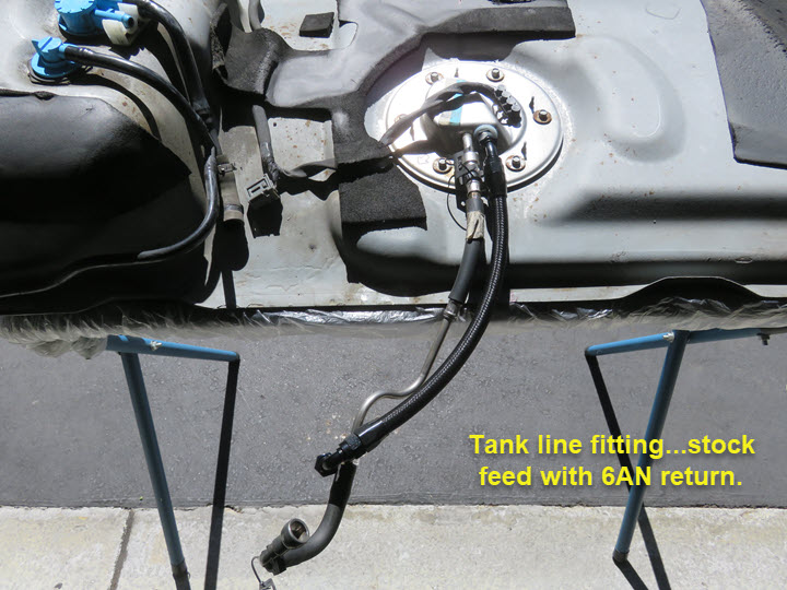
While the tank was out I installed a new 340LPH pump to insure I had enough fuel to run the Coyote. Removing the pump wasn't too hard, just need to snake it around a bit to get it and the sending unit (all one piece) out of the tank. The tank was clean but I cleaned it more. Installed the new pump (PNP) and inserted it back in the tank after drilling and installing a bulkhead fitting for the return line. I had to "massage" the trunk spare tire area a bit to make sure I cleared my fitting and hose. There's not a lot of room, but I wanted to make sure. I'm thinking I may cut a round hole in the spare tire area and make a cover for it to access the pump later if needed.
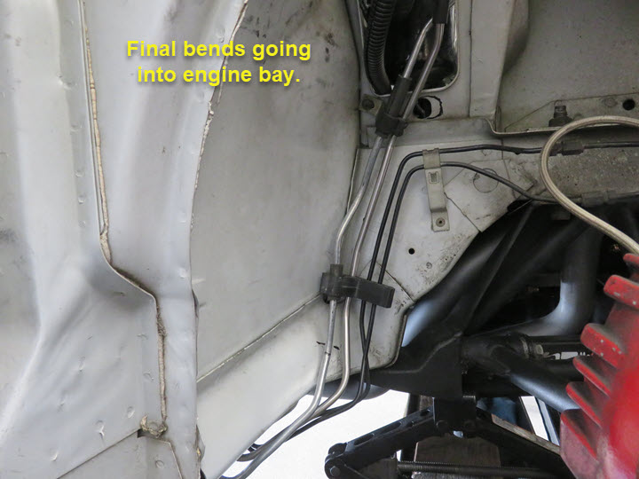
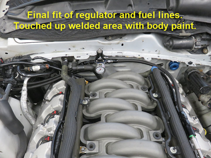
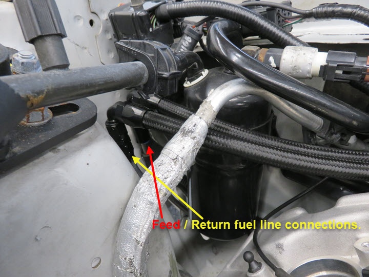
Once the lines were in and secure I test fit the fuel tank to insure the hose would clear my Panhard Bar setup and lower trunk area. All worked out o.k. and I used a 45deg. AN6 fitting at the fuel hat where I inserted a bulkhead fitting for the return line. The steel return line came out just behind the stock fuel filter, which I was able to keep and use all the stock feed hoses. At the engine compartment side I have them both in the stock "entrance area" in the frame. I removed the fuel damper hose assembly from the feed line and ran a EFI 6AN fitting to a hose and then to the regulator which I installed at the firewall. The return line had a compression AN6 fitting and then hose to the regulator. All of this turned out great and has a nice clean look.
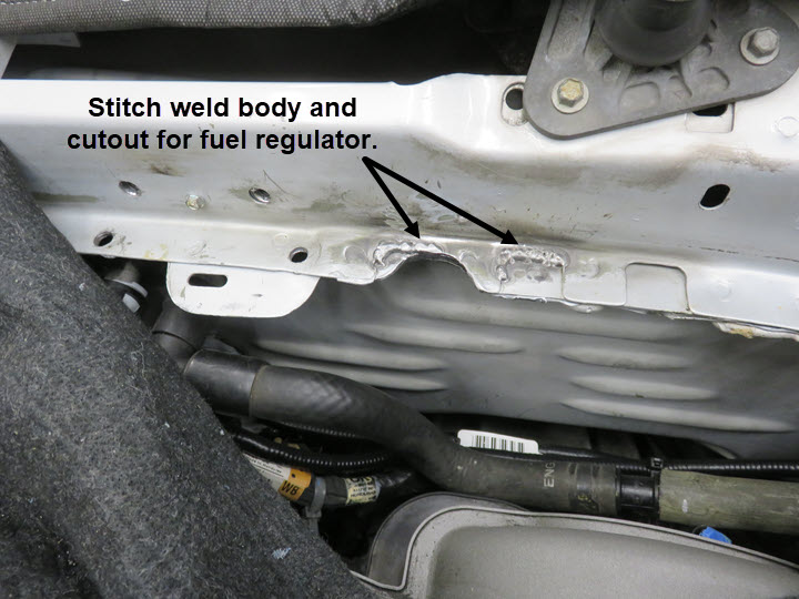
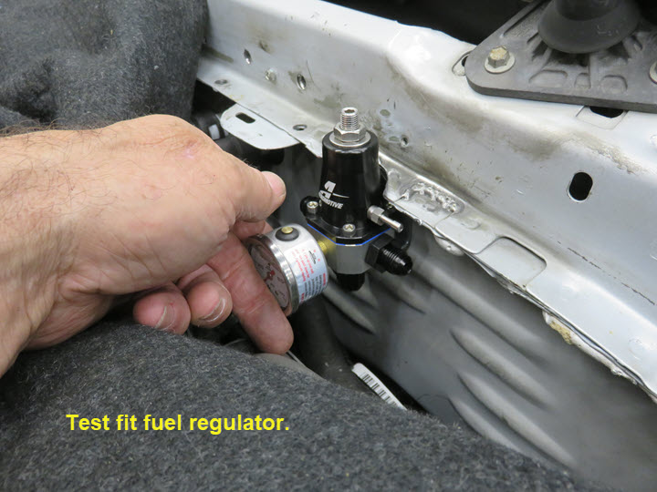
I had to figure out where to put the regulator due to the lack of space available under the hood. I came up with a firewall location and positioned it to the side of the intake runners on the right side so it would clear. I did some stitch welding after cutting out a small half moon shape to allow the regulator to fit close to the firewall. Very pleased how this came out and everything cleared and hoses ran without kinks.
Cooling System
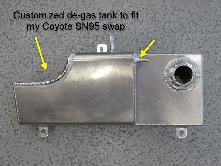
Once fuel was done it was time for the cooling system. My goal was to keep the existing setup as much as possible, but the de-gas tank wouldn't fit. I ordered a Moroso aluminum stock 4.6 tank and did some customizing to make it work. Due to me keeping the battery up front and the air intake going to the right, I cut out part of the tank in an arc to go around the inlet hose, but kept as much of the tank as possible for capacity/cooling purposes. This worked out great and also installed another bung for the radiator overflow in the tank.
Next was figuring out the heater hoses. I was able to keep both the Coyote stock hoses and trim the ends that went to the heater core. The left side was cut near the back of the intake and connected with a 5/8" hose coupling to my existing 4.6 heater hose. The right side was trimmed near the heater core end and I purchased a Gates 28502 quick connect hose fitting to attach to the hose and reconnect to my heater core. Problem solved! Replacement hoses are now stock 2013 Coyote and stock 2002 4.6GT.
Radiator hose layout was next. This took some thinking on my part and trial and error to make it all work. I was able to source (from sn95forums.com) a good lower hose replacement. Due to the 4.6 radiator having a 1 3/4" outlet and the Coyote a 1 1/2" outlet, I needed a step-down type hose. I found a Gates 22900 hose for a Jeep Cherokee would fit and just needed to cut part of it off for what I needed. The other end connecting to the thermostat housing was the actual lower Coyote hose trimmed and reversed along with a 4" x 1 1/2" aluminum tube to connect them together. This gave me good clearance from the power steering pump/pulley area and fit perfectly. It'll take two hoses to make up the lower connection. The upper hose turned out to be easier. I tried the stock Coyote hose but it just wouldn't clear the area I wanted by the alternator and had too much "kink" for me to be comfortable. I ended up using the stock 4.6 upper hose trimmed at the radiator end by 1/2" or so and then again about six inches in, used another 3" x 1 1/2" aluminum tube, connected to the remaining 4.6 hose trimmed and reversed, along with the Power by The Hour aluminum upper hose adapter and connected it all together. Reversing the remaining part of the hose gave me the needed slight "S" bend to connect without any "kinks". The de-gas tank needed another splice type setup and was able to get a 1" x 3/4" 90deg. reducing elbow hose (Pegasus Auto Racing) and connect with another Gates 28474 3/4" 90deg hose to make the block connection. The remaining 3/8" hoses for the air bleed were stock and just trimmed to fit.
Power Steering
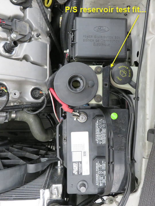
As problems showed up, I had to find a solution and the power steering reservoir was no different. Due to the fact it bolted to the front of the 4.6, there's NO room for it on the Coyote with the configuration I have, so I had to find a solution. My goal is to keep the stock power steering setup and utilize what I have. The Power by The Hour speed drive setup allows for this so I came up with a solution.
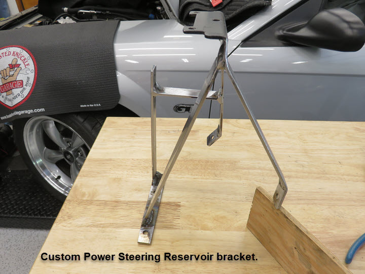
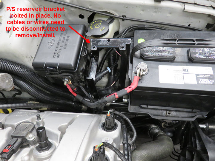
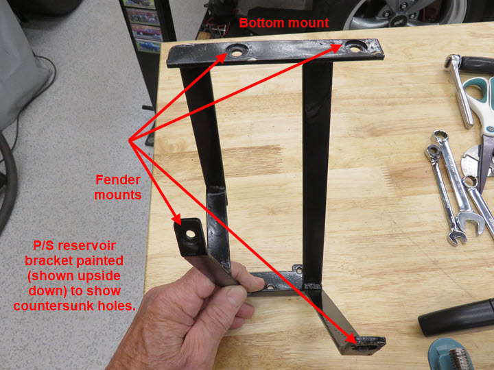
I researched and found many who moved the Power Distribution Box (what an ordeal) forward and mounted the reservoir in that area using the bracket supplied by several vendors including Power by The Hour that bolts to the left head. Problem there is, 1: vibration and 2: needs room. In addition it means moving the battery somewhere else! However, I wasn't about to do that, nor was I inclined to move the battery to the trunk area. So, I was able to move the battery forward one inch and made a custom reservoir bracket (using part of the old one) and secure it to the chassis/fender area using 1/4"-20 nutserts. This took a couple of days, but allowed me to use all the stock battery cables and Power Distribution Box in its stock position. I was also able to use the existing feed hose to the pump (trimmed) without needing a special hose. The other "TEE" hoses were trimmed and a new "TEE" was used to connect the return lines. My next goal is to remove all the existing pressure lines and go to an AN setup.
With all the wiring, hoses and battery cables intact, I'm able to remove the entire reservoir and/or bracket without disrupting any connections other than disconnecting the battery NEG cable for safety. Not bad at all! The battery tray was moved forward one inch, secured by new 1/4"-20 nutserts in the frame and fender area and the stock full sized battery is still there. It's a tight fit, but I made it as easy as I could to do any type of service work.
Once all this was done I was that much closer to test firing the engine to see if all my connections and wiring were good.
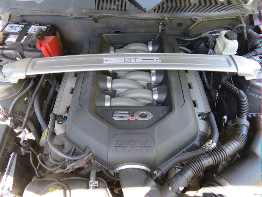
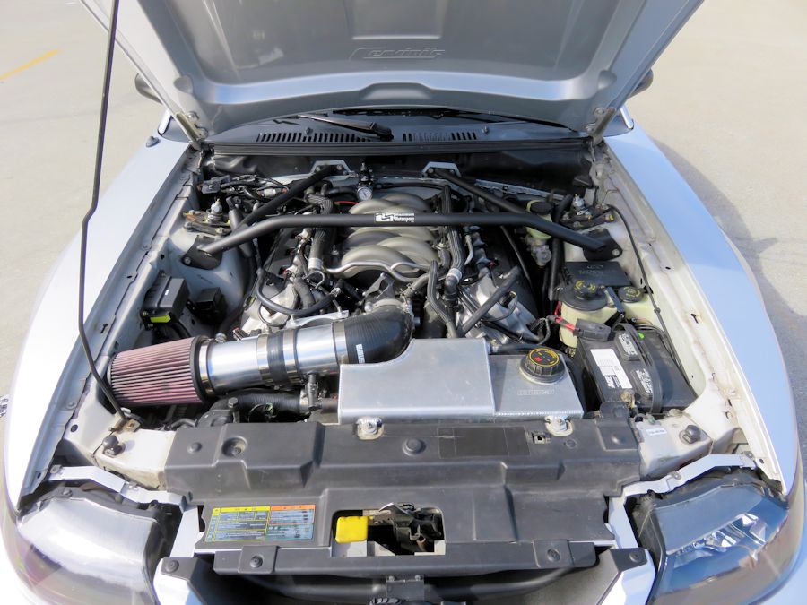
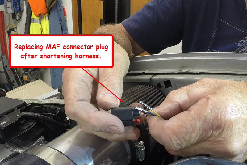
Air/MAF Intake
My plan was always to try and keep as many items stock as possible while doing the swap. This included running the air intake to the right side. Coyote's are naturally run to the left, but that's where the battery is and I planned on keeping it there. I used the Power by The Hour air intake kit in order to keep it all stock and not have to make a special "tune" to the PCM. They're MAF adapter is perfectly made to accept the MAF without any mods. Also, the tube in the kit can be made to any length you need (provided you don't need more). Once installed, the air intake made a nice transition to the right side and I may try to make an enclosure for the filter to help keep hot air from getting in easier. I made a simple brace to help keep the entire intake assembly from sagging, which is attached to one of the alternator bracket nuts. I also purchased a couple of Quick Disconnect PCV 90deg. fittings and made a new breather tube to connect the valve cover vent to the air intake tube. Trick here was using some slow drip irrigation hose, heating slowly while bending and then attaching the fittings. Covered the setup with some heat sleeve. Pretty ingenious of me I think!
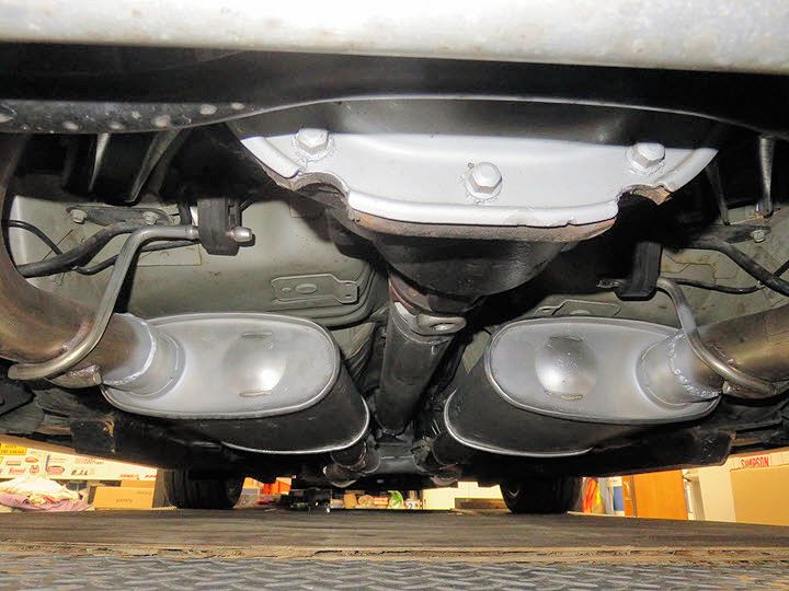
Exhaust Changes
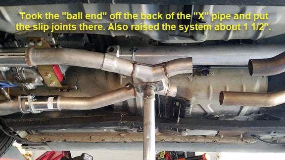
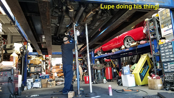
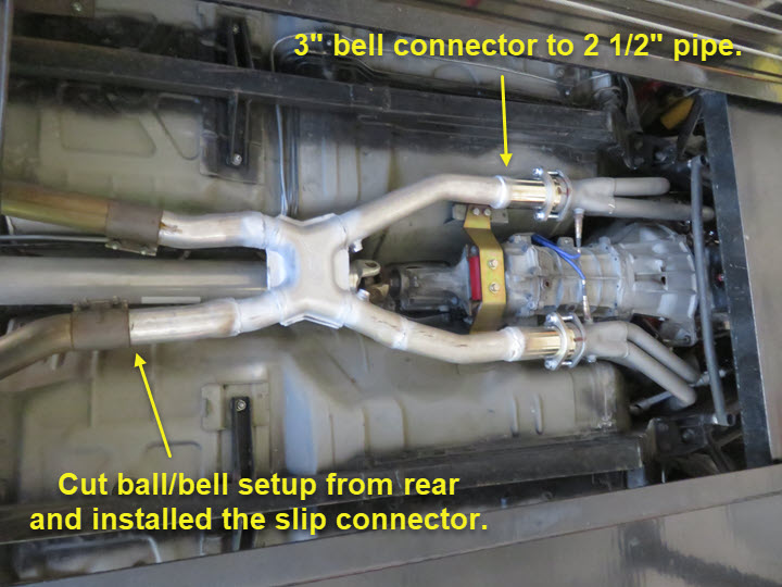
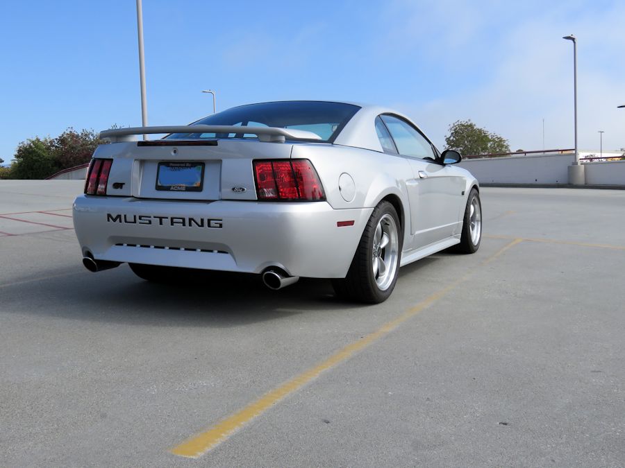
After making my track event earlier in the month, I got busted for sound (with my Borla Type S mufflers) violation! Wow, that was a first and never happened with the 4.6L, so I attributed it with the fact the Coyote is much louder and efficient, as well as me running it up to 6500rpm (just to see) how far I could go. Just happened to be at/near the sound collection area. I talked to my exhaust guy Lupe who was at the event and he told me the Dynomax Turbo would be a good change, so I scheduled a date after the event and got them installed.
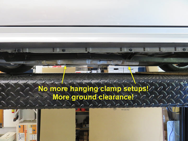
Once on, they fit much better and are now higher than my Maximum Motorsports full length sub-frame connectors, so they are tucked up nicely. They are quieter at idle and cruising speed, but when you open it up past 5500rpm, they let you know!
On a side note: doing my last track event in October 2022 at Laguna Seca Raceway (also known as the quietest track on the coast), I requested a sound check with the new Dynomax Turbo mufflers installed and blew an amazing 88.6db, which is fantastic! This will allow me to hit many of the 90-92db track days. I also doubt it made any acceptable loss of power on the Coyote.
Thoughts and Analysis
Question asked is why? Answer is always, because I can. Bottom line is it was fun, exciting, frustrating, time consuming, challenging and any other verb you want to use to make this possible. For the most part I did 99% of the work myself with very little assistance from anyone. My wife when needed was always there and I did rely on a friend to help with the tig welding on my degas tank. Other than the exhaust work, it was all me. Of course, having others who did this before and being able to see "some" of their attempts helped, but for the most part, I did a lot of digging for answers and finding solutions myself.
Searching many YouTube videos and websites touting they did swaps, I found a LOT of missing or just not mentioning information needed to really make it sound as easy as "plug-n-play". It is definitely not for a weak pocketbook or lack of patience. You need both. Having someone you can trust is another key component to guide or help you along the way. Hopefully some of what I have here will allow you to feel better about attempting or doing this swap. It can be done, and isn't too hard if you take your time and understand the needs you want. Would I do it again, yes! Knowing what I know now and how to deal with the issues, I'm sure I could do it much quicker, and just as clean.
My build/swap took me almost two months to the day to complete. I worked six to eight hours a day on average taking off a couple of weekends for other things. I have a well equipped garage and knowledge I've gathered along my career which helped immensely. I had a goal and met that goal. I think the worst thing to do would be start the project, become bored, and then quit. Bottom line is be committed! My YouTube channel covers my build and I don't leave things out. I try to cover the small things that you don't or forget to think about. If there's something missing, let me know. Again, this build was a Gen 1 Coyote, but the Gen 2 & 3 aren't too much different.
Getting this done and making my track event(s) was the icing on the cake. I was able to stay with or overtake others who could/would always pass me before. Not a big deal because it is just open track and just for fun. However, having this power in a SN95 New Edge Mustang that is 600-800 pounds lighter than a S197 or S550 is a huge improvement! Now I can sit back and enjoy my work!
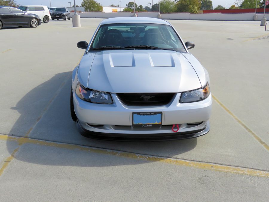
One thing I planned for prior to the build was a new hood. I opted for the Cervinis Heat Extractor hood. In my opinion, it looks much better than the stock scoop hood and will allow a lot more heat out of the engine compartment, where the stock hood was solid (scoop being fake). I also think it dressed the car out very well and now has a nice stance to it. Next step is the front bumper/splitter area.
Fuel Tank Modification...Holley Hydramat...Sump Modification
On to my next project. Installing a Holley Hydramat to hopefully cure my 1/2 tank or less high "G" fuel starvation in corners when on track, was going to be my next modification or upgrade to the fueling issue.
However, I decided to take a chance and do a little "test" before committing to the Hydramat.
The stock fuel/pump/tank is a convoluted plumbing nightmare, only when you have a return style system I guess. Normal driving does not effect the operation of the car, just being a little over zealous in corners on track pulling high "G" force and mainly left hand sweepers or long curves, and also with 1/2 tank or less of fuel. I could always keep it full, but why? I'm going to attempt this and then test it in a few weeks at my first event of the year, so here goes...
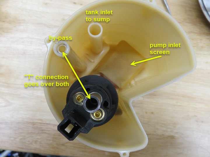
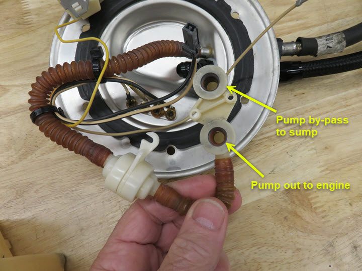
The plastic sump shown holds the fuel pump and sender and snaps into the holder, which is fused into the tank bottom. In other words, it holds the pump and is held in place by the "top cover" of the sump. You can see where the top outlet goes to both the pump and by-pass tube. The by-pass just goes back into the tank and also to the inlet side via another "T" shown below. I do need the sump assy. because it holds the fuel sending unit and pump secure.
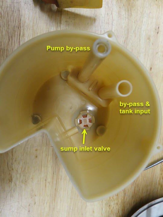
The following is just a shot of the sump and the small flapper inlet to the sump from the tank, which really seems useless, but does act as a stopper when fuel is pulled into the sump via the external mounted screen/sock. Notice the by-pass & input tube doesn't go to the top of the sump.
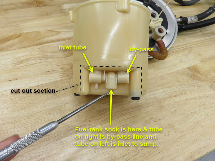
This is a side shot of the sump showing the two tubes and the "T" connection between them, that connect to the inlet screen sock as well. All of this can/could get pulled back into the sump. I have also marked with dash lines where I would remove a section of the sump so the Holley Hydramat will be able to go into the tank itself. I'm not going to need the sump per say, as the Holley Hydramat will be the new sump (I hope). I can't just cut up the sump due to it needing to hold the pump and sender, so I have to be surgical about it. I just found it strange how pressure is directed back to a "T" to the tank and also connected to a tube back into the sump. The true inlet to the pump is the little flapper/screen in the bottom of the pump where the pump screen pickup is.
Now, having said all of that, none of it is being done at this time, because I came up with a brainstorm while talking to a buddy of mine. His suggestion was to drill holes in the side of the sump about 2/3rd's of the way up. After thinking about that idea, it occurred to me that really wouldn't help the problem of it starving for fuel when the tank is low. I then had a brainstorm and thought about drilling a hole in the top hat of the sump and directing my return line directly into the sump instead of letting it just spray into the tank when returning from the regulator.
This is showing the "T" connection on the top cover that is needed to connect the pump and by-pass, and you can see the two small holes for screws that keep this secure to the pump and "sandwhiches" it from the cover to the sump bottom. I have to make sure the Holley Hydramat and cover tightly keep the pump in place.
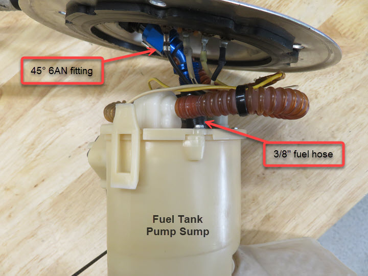
Now that that's clear as mud, my solution for this test is to put a 45deg. fitting on the return coming through the tank/pump hat and directing it into the top of the sump hat, drilling a hole and attaching some fuel line to the fitting to make sure it gets into the sump and not into the tank itself. The sump is NOT an air tight unit so I'm not worried about fuel getting out once in the sump or the possibility of it expanding due to pressure.
I took a 45deg. fitting I had and removed the hose nut and put a piece of 3/8" fuel hose to the end and zip-tied it to the fitting to keep it in place. The fitting had a barbed end so not too worried about it coming off (for now). As I said, this is a test. After taking some measurements where to drill the hat, I drilled a hole and put the hose and tank hat back together and stuffed it back into the tank, making sure the hose stayed in the sump. I could've used a longer piece of hose, but did get it to stay put. So, basically the only thing that was done was drilling a hole to allow the return back into the sump. I did think about foaming issues as well as cavitation and the like, but would just have to see how the engine performed. The sump is only about one quart capacity and the only other test I may do is to see what kind of fuel return and time it takes when the pump is running. The pump is a 340LPH and is constantly running so I doubt it's not keeping up with the requirements of the Coyote. I have a My YouTube Channel video on my site showing what I did Fuel Tank Pump/Sump Mod.
After the tank was put back in, I put 5 gallons in to see where the gauge registered (1/4 full) and then another 5 gallons and noted that (about 5/8 full). I had a track (Thunderill Park) event coming up that weekend so it will be put to the test. My goal is to purposely run it to at least 1/2 tank or less and see what happens. I would have to know when that happens so I can prepare for the sudden loss of power when/if it still happens. I began my day with a full tank and by the afternoon it was time for testing. I ran it below 1/2 tank slightly and nothing happened. I decided to fill it for the rest of the day and not put more fuel in for the next day.
Starting the day with about 3/4 tank of fuel. Took it down to under 1/2 tank and car was performing as well as expected with no hesitations at all. My final session started with just over 1/4 tank and I reminded myself that I'd better be prepared for stalling and/or loss of power on a few sections of the track. Well, I forgot to remind myself to watch the gauge and proceeded to run the heck out of it for the entire session. Yes, I made it through the session without a hic-up and loaded it on the trailer. Only then did I remember to check the fuel level. Upon my surprise, the gauge read about 1/8 of a tank, which told me the issue I was having is no longer present. So, as of this posting, I'm confident of the modification. However, I do have another event in a month and will give it another test. That test will be at the same track (Sonoma Raceway) that I discovered the problem to begin with. I'm hoping for positive results and will post them here afterwards.
Sonoma Raceway, Fuel Test #2Again starting the day with a full tank of fuel. Took tank down to less than 1/2 tank by mid afternoon with no starvation at all. Filled up to finish the rest of the day (2 sessions) and be ready for the next day knowing I'll run at least three more sessions without fueling up. As I got ready for my last session the gauge showed just over 1/4 tank and I finished the session without incident on starvation. After returning home, I took it to the station to fill up and put just over 13 gallons in the tank. This means I took it down to just over 3 gallons remaining and had no hesitation, miss, fart or anything else resembling a starvation problem. I'm fully satisfied this took care of the problem I was having and will now enjoy track days even more.
Problem Solved!!
Holley Coyote Swap Oil Pan
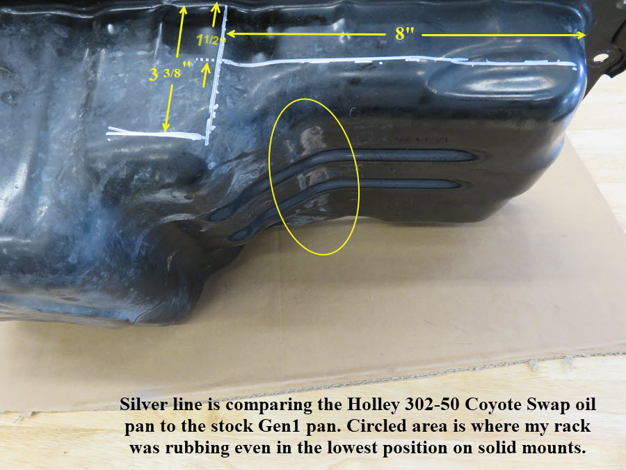
After a years worth of street and track driving I was noticing some chatter coming from my clutch. Remember, I put my used, but new, Centerforce Dual Friction clutch in the Coyote because it was in good shape. My plan was to remove it and check it just to be sure, knowing that it would be a royal pain to remove it, due to needing the long tube headers remove first. Upon further notice, I found my steering rack was now touching. Or you could say the engine was resting on the rack. I had lowered my rack as far as possible when doing the Coyote install so I had to come up with a solution. After doing some research I found the Holley Coyote Swap Oil Pan, part no. 302-50, and it looked like a good choice.
Knowing what a PITA it is, I started by baring my engine on the top for support and realized it would be much easier to just remove the suspension and K-member so I wouldn't have to fight things. I looked at it like a puzzle, so every step and piece was thought out.
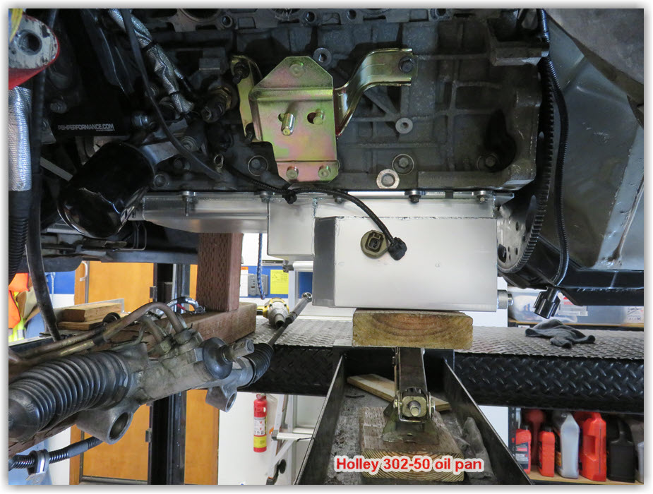
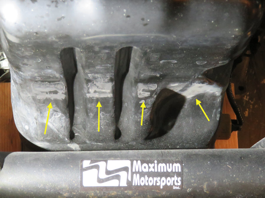
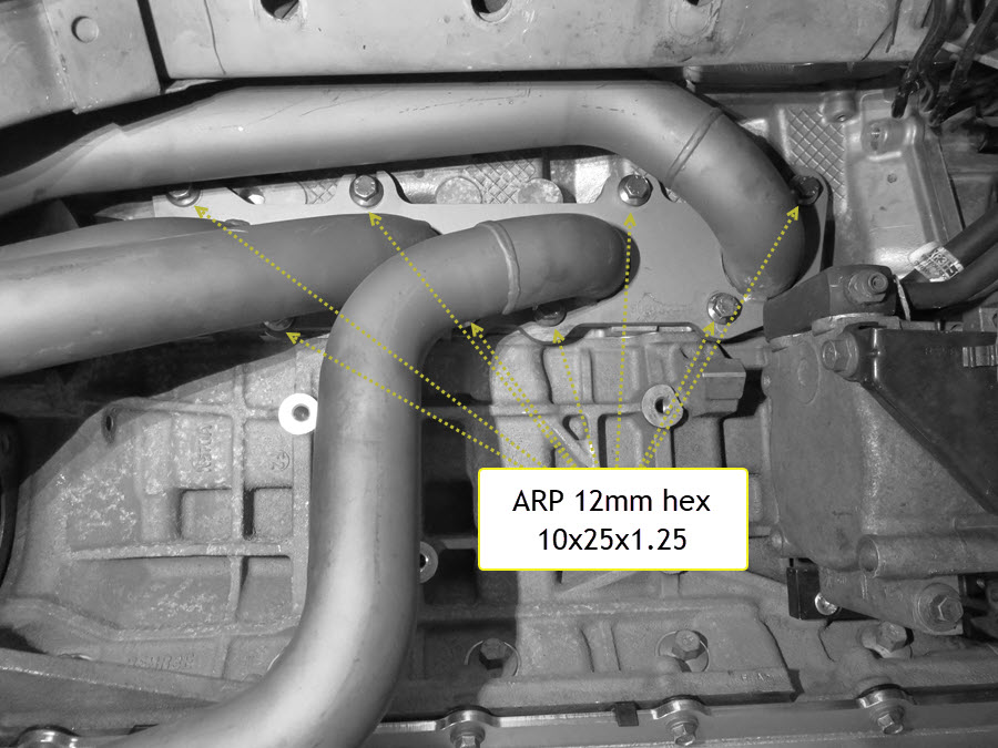
Remove the suspension all the way to the K-member, tying up the struts and brakes. Next step was remove the steering shaft, rack, K-member, then motor mounts and starter, so I could have clear access to the header bolts. I had mix of hex heads from the BBK kit, so when replacing them, I went with ARP 12mm hex head bolts (10mmx1.25x25mm) so they'd all be the same. Glad to have them on the install! Once the headers were out, I started the removal of the oil pan. At this time I had pulled the transmission. Once the pan was off, I followed Holley's installation instructions and made sure I had the required space between the new pickup (included with the pan) and proceeded to install the new pan. I also purchased a new pan/baffle gasket to insure I wouldn't have an issue, although the old one could've been reused. The Holley pan is nice and equipped with the low-oil sensor bung, as well as a front return bung 10AN O-ring boss (plug not included) and a rear 3/8 NPT drain plug. Mocking up the pan is easy and I opted for taking measurements and doing math rather than using modeling clay and then checking sump to pick-up clearance. I did mock-up the pick-up (minus the O-ring) and gasket to take my measurements and subtracted that from the pan depth. I ended up with a strong 5/16" which was within their specifications. Installing the front pump pick-up tube bolt requies a modification of a 1/4" drive 10mm deep socket so you can tighten the bolt. Due to the pick-up being closer to the main caps, the clearance is tight, where removing the stock one I was able to just use my 1/4" drive 10mm universal socket.
I inspected the clutch, found it to be good, but because it was out again, I opted to install a new one. Put the transmission back in, bolted up the K-member, removed my engine support bar, motor mounts and found the headers didn't have enough clearance between the engine and body as before and then realized the oil pan had an inch wider "T" on each side which prevented just enough to not clear the headers. I quit for the night so I could think on it.
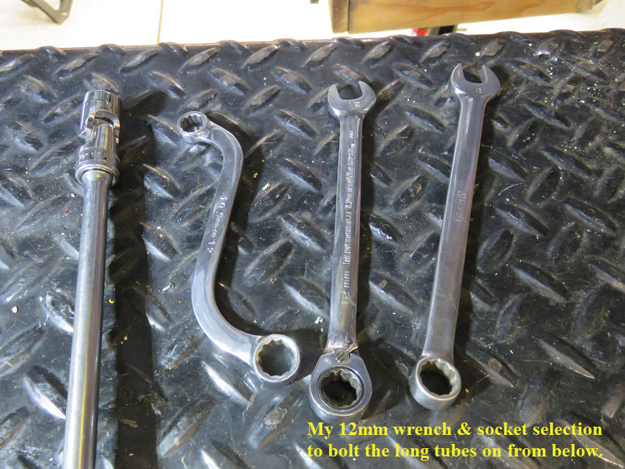
After giving it a lot of thought and figuring out, I decided to pull the K-member back out along with the starter and motor mounts so I'd have as much room as possible to get the headers on. Problem was...I had my engine support bar off, so I put my transmission jack and some blocks under the front of the oil pan and jacked the engine enough to clear the K-member. Now I could remove the starter and motor mounts to get ready for the header installation. Plenty of "small" room to get all the header bolts started. Still need to start a few of the upper header bolts in the head with the exhaust gasket and then slide the headers into place via the slots on some of the flange areas. It was just a matter of using a selection of 12mm wrench's to secure all the bolts. Next was installing the starter and then both motor mounts. Next was settling the engine back in the K-member, putting the steering rack and shaft back in and finish buttoning it up. See, it's a puzzle!
The pan install is also on my YouTube page if you want to see what/how I did the work.
I do have the advantage of using a lift and my four post lift works perfectly. In the future it'll be, remove all the suspension stuff, jack up the front of the engine to clear the motor mounts, support the transmission (jack or jack bridge), remove the K-member, motor mounts and starter; then remove the transmission to get to the clutch. Either way, lowering the engine/transmission package would require the same amount of work to accomplish the same thing for me, and, the K-member would still need to be removed because I can't get it cleanly between my ramps (misses by a couple inches) and the headers could pose the same problem. A twin post would be better, but I use mine for more than a work area, plus I only need to drain the transmission.
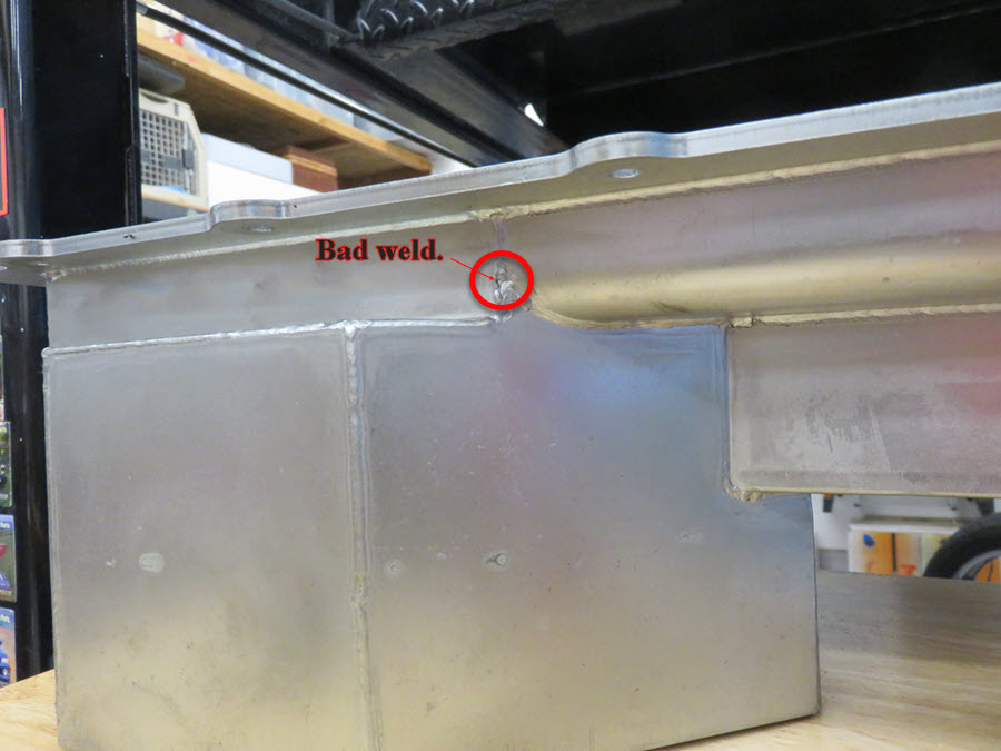
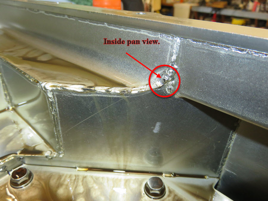
Holley Coyote Swap Oil Pan...Leak
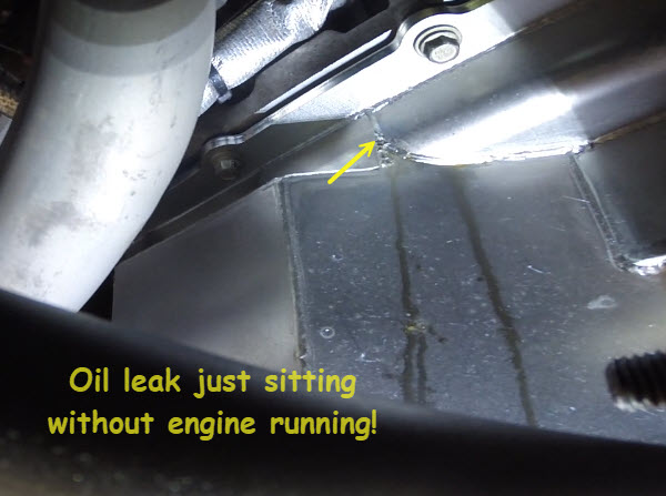
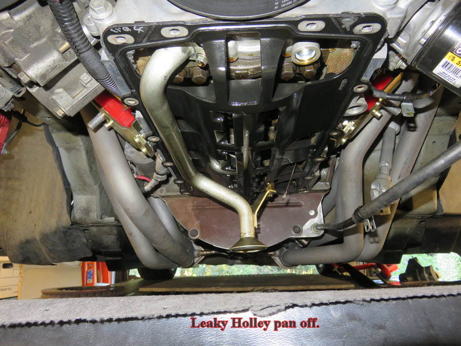
Sometimes it just doesn't go well. In my case, the workmanship (on my part) was very good. However, the workmanship on Holley's part, not so good! After doing my track event and getting back home and on the lift, I went about my normal duties and a week later took a look under the car and noticed an oil leak on the pan. Not being sure where it was coming from, I decided to inspect all my work carefully and then wipe down the pan clean and let it sit to see if it was caused by pressure or just gravity. After a few hours I noticed a stream/leak coming along the bottom of the pan and followed it to the source. OMG! It was coming from a weld seam about 1/2" below the top of the pan. Now it was time to do the entire job, sans the exhaust off, again and replace the pan. With the leaky pan off, I inspected the area with a light in the dark and BAM! Pin hole leak right at the area in question, so I knew that was the problem.
Being the pan was still under warranty, I opted to purchase a new pan to expedite my repairs. I also knew I was going to inspect every weld/seam on the new pan, as well as change out the NPT drain plug to a more civilized normal plug with washer setup. So, being in the area of Summit Racing, I picked up my new pan and after getting back home, started the process.
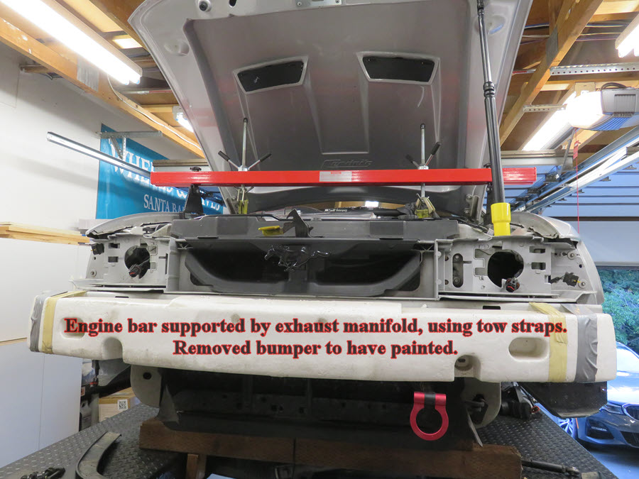
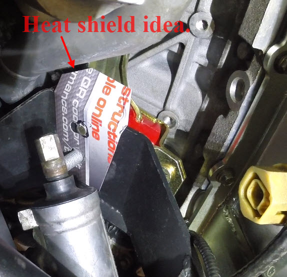
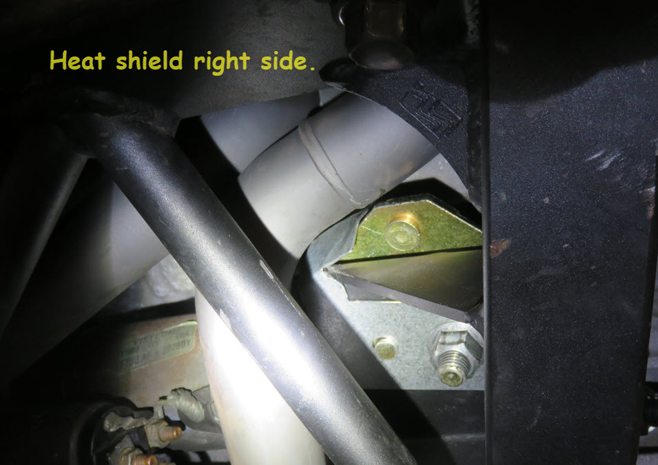
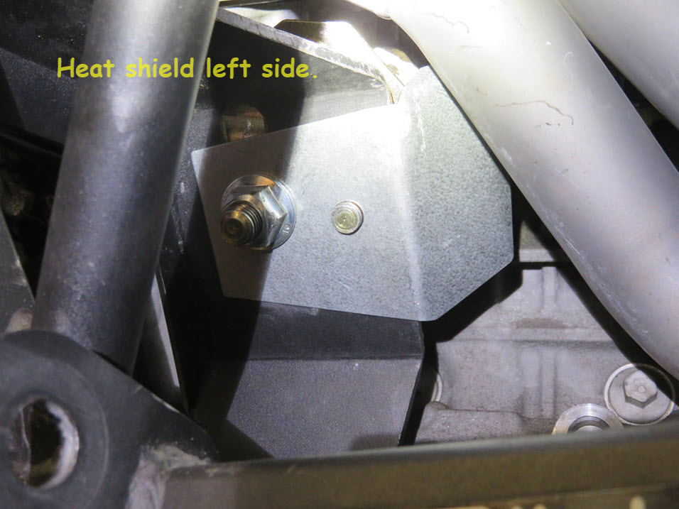
Knowing the exhaust didn't need to be removed, I used a strap on each side attached to my engine bar to support the engine. The rest was fairly straight forward with removing the entire front suspension again and getting access to the pan itself. I did notice some new blisters on my new motor mounts, so I made some heat shield templates and once the K-member was removed, made some shields out of metal to install once I was done. I also got a 16.5mm drill and 18x1.5mm tap to drill and tap the NPT port to accept a new 18mm magnetic drain plug and installed that with a metal/rubber gasket. I filled the new oil pan with water and plugged all the ports, let it sit for two hours and hoped for no leaks. After sitting and inspecting, it all looked good so on the engine it goes. Process was the same as before and didn't remove the oil pickup because it's the same on. Checked the depth measurement and it was good as well. Gasket was new so just put some silicone sealer in each of the "split" areas and a swipe front and rear of the pan and on it went.
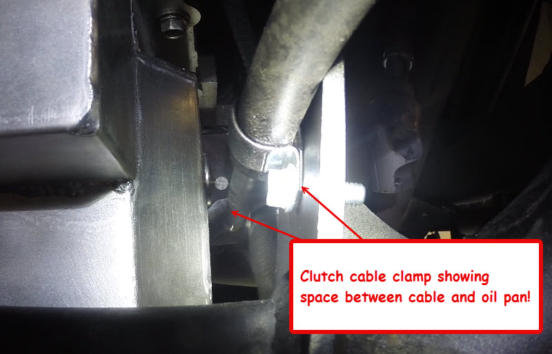
While the K-member was out, I had marked a spot to put a cable clamp over my clutch cable so I could bolt it to the K-member to keep it off the hot oil pan. I drilled a 1/4" hole and put a bolt/nut on the clamp after the K-member was back in and it worked out perfectly. Also keeping the cable in a nice straight shot to the clutch fork. All this is on my YouTube page.
I had also removed the front bumper to have it re-painted. It had a bunch of peeling paint and bubbles from when I purchased the car and it just bugged the hell out of me. So I took it off while doing the oil pan job and took it to my buddy Brian at AA Auto Collisionto get it done. I replaced all the small hardware and plastic connectors and now that job is done too! I replaced the small air dam below the radiator as well.
While the bumper was off, I removed the right fender to do more work on the PCM harness. I shortened another section of PCM harness another 13" to remove a "loop" I left in during the original wiring. Just too anal I guess, but it looks much better. Also removed about a 3' length of harness to the MAF and got a new plug and terminal ends to make it a custom fit. Along with that I put the OSS Coyote wires (3) back in the PCM harness to see if it would help stop the occasional dying coming to a long slow stop and depressing the clutch syndrome. Have to wait and see on that. Also plan to move my crank sensor pickup wire from the 42pin connector that runs up front, where the Coyote PCM is, and put it at the rear of the block harness closer to the Coyote crank sensor. Maybe that will keep the tachometer working smooth between 1500-2000rpm.
I changed out the copper crush washer on the drain plug because it didn't really seal that great. I purchased some 18mm steel/vitron plug gaskets and they will solve the issue. There is NO leak from the plug! Filled it with new 5w-50 oil and started up. No leaks and all is good! Again!!
I also needed to clean up some dash and door panel pieces, and purchased new (reman) door pulls and took the dash center and gauge bezel out to repaint. I didn't like the gray color that surrounded the gauges so I painted it a SEM 15013 Landau Black color which is real close to the black colored trim. It definitely helped show the white backed gauge cluster, without the distraction of several colors behind the steering wheel.